For high-performance engines—whether it be the BMW S58, Audi EA837 3.0T, Mercedes-AMG A45, or VW EA888—thermal management is a critical component. Factory cooling systems often struggle to cope with the intensity of track driving or the rigorous operating conditions that follow power upgrades (Tuning). It is for this very reason that we developed the Pro Cooler—a comprehensive cooling solution that combines precision CNC-machined end tanks with advanced graphene coating technology, designed to deliver unparalleled heat dissipation performance. *Note: Not all Pro Cooler models incorporate both features; please inquiry us for specific details regarding individual models.*
What Makes the Pro Cooler Unique?
1. Graphene Coating Layer
Unlike traditional paint or anodized surface treatments, the Pro Cooler features an ultra-thin graphene film that presents a refined "semi-matte" finish—neither fully glossy nor completely matte. More importantly, this coating possesses "thermal impedance reduction" properties, meaning it significantly outperforms standard painted surfaces in terms of actual heat dissipation efficiency. Whether applied to intercoolers, radiators, or oil coolers, it extracts heat at a faster and more consistent rate.
2. Precision CNC-Engineered Tanks and Core Technology
The end tanks on select custom cooling within the series are precision-designed and machined using CNC technology, ensuring flawless fluid distribution and exceptional structural integrity. For specific vehicle applications—such as the BMW X3/X4 B48—we utilize an enlarged cooling core. This core is twice the thickness of the factory component and features a fin pitch of 6.8mm paired with a fin thickness of 0.1mm—a parameter combination validated through extensive testing to strike the perfect balance between low airflow resistance and high thermal efficiency, thereby ensuring optimal airflow throughput.

3. Engineering Tailored to Specific Vehicle Models
The Pro Cooler is by no means a generic aftermarket accessory attempting to offer a "one-size-fits-all" solution for every vehicle model. Tailored specifically for the following models—or contact us anytime for custom design inquiries regarding other vehicles:

BMW X3M / X4M (S58) — Charge Air Cooler & Intake Manifold (Available in Black, Silver, or Red)
Audi EA837 3.0T (A6/A7/S5/SQ5)
VW EA888 — Available in 25-Row, 27-Row, or 29-Row configurations
Porsche 911 (992 Intake Plenum; 991.2 Turbo Y-Pipe) — Features Carbon Fiber Air Ducting Components
Mercedes-AMG A45 W177 — A complete, avant-garde cooling upgrade solution
BMW F80 — Intercooler, Main Radiator, Auxiliary Radiator, and Oil Cooler
Why Choose Pro Cooler?
Graphene coating offers not only a stunning aesthetic but also actively aids in heat dissipation, thereby enhancing real-world performance.
Precision CNC-machined end tanks completely eliminate the structural weak points inherent in traditional stamped seams, while optimizing the flow distribution of both coolant and charge air.
Signature Aesthetic Craftsmanship — Creates a clean, modern, and highly professional visual impression within the engine bay.
Core Value Summary
Pro Cooler is far more than just an oversized radiator or a visually appealing intercooler. It represents a comprehensive, all-encompassing cooling solution that seamlessly integrates cutting-edge material science (Graphene Technology) with precision manufacturing processes (CNC Machining). Whether you are pushing a 992 to its limits on the track, heavily tuning an EA888 engine, or unleashing the full power of an S58-equipped X3M—Pro Cooler effectively suppresses Intake Air Temperatures (IAT), ensuring consistent, robust, and unwavering power delivery.
Ready to Upgrade?
Contact us today to receive a tailored solution for your specific vehicle model—and equip yourself with a premium cooling upgrade kit engineered to push the boundaries of manufacturing craftsmanship, surface coating technology, and engineering design.


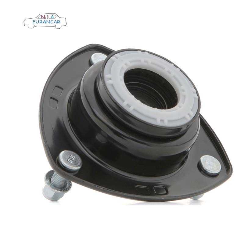
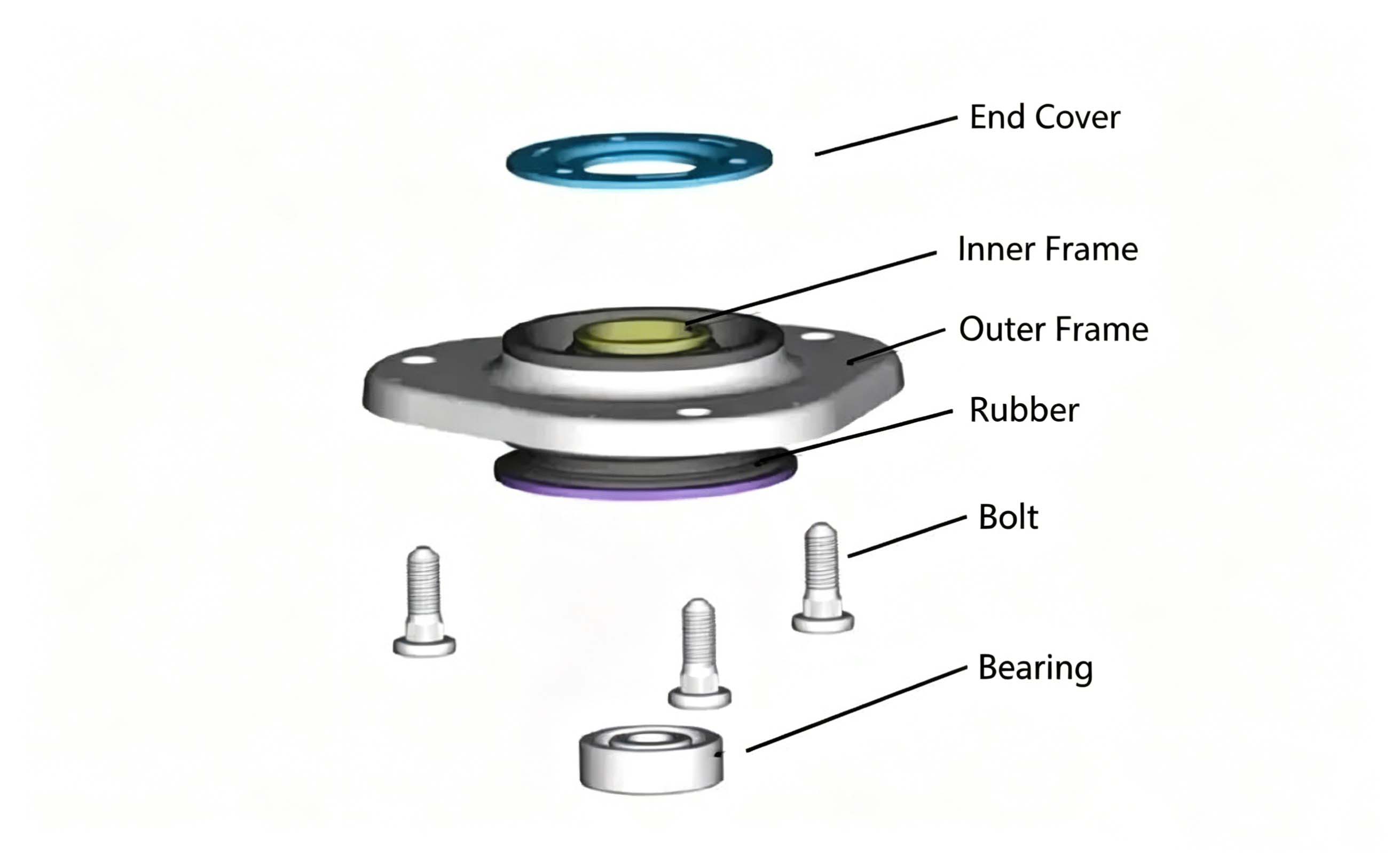 The shock absorber top mount is made of rubber and serves to cushion and absorb vibrations. When the spring is fully compressed, the vehicle body is subjected to a relatively strong impact transmitted from the wheels; without the cushioning provided by the shock absorber top mount, this intense impact would not only damage the shock absorber but could also cause the wheel hub to deform.

