Basic knowledge of car seat slide rails

1. What is a car seat slide?

The slide is an important mechanical component on the seat. The common slide is mainly installed under the seat and is used to adjust the front, back, left and right positions. It usually consists of two parallel tracks and a sliding mechanism. By operating the adjustment handle or button on the seat, the seat can move smoothly forward and backward on the slide to meet the riding needs of different drivers and passengers.

The slide is generally composed of upper rails, lower rails, locking mechanisms (manual), adjustment mechanisms (electric), ball rollers and ball roller cages.


Car model slide rail

 Manual sliding rail

Manual sliding rail


2. The role of the slide

(1)Adjust the position of the seat to facilitate the driver to adjust to the appropriate position and control the car; or to allow passengers to get a more comfortable space.


Slide rail fore and aft adjustment


(2) Ensure the strength and rigidity of the connection between the seat and the base plate, so that the seat can maintain the sitting posture when the car is hit, increasing safety.


Strength test of seat belt fixing point


3. Classification of slides

3.1 According to the drive:

① Manual slide: You need to pull the towelbar to unlock the slide, and then push the seat to slide. According to the position of the unlocking handle, it is further divided into built-in unlocking manual slides and external unlocking manual slides.


Built in unlock manual slide rail


External unlocking manual slide rail


② Electric slide rail: The slide rail that automatically adjusts the front and rear of the seat is driven by a motor. According to the different positions of the motor, it is further divided into a central electric slide rail and a front electric slide rail.


Mid mounted electric slide rail

Front electric slide rail


3.2 According to the stroke:

① Ordinary slide rail: A slide rail with a shorter adjustment stroke, generally about 180mm-260mm.


Ordinary slide rail


② Long slide rail: Adjust to form a longer slide rail, with a stroke of about 400mm-1500mm.


Long slide rail


3.3 According to the adjustment direction

① Longitudinal slide rail: The most commonly used slide rail, the slide rail that the seat can move in the longitudinal direction.


Vertically adjustable seat


② Horizontal slide rail: The slide rail that the seat can move in the horizontal direction is mostly used in some MPVs (Odyssey, Elysion, etc.).


Lateral adjustment seat


③ V-type slide rail: The slide rail that the seat moves at a certain angle along the longitudinal direction in the car, and this slide rail is less used.


V-shaped sliding rail seat


3.4 According to the rail type

① W-type rail (M-type): The cross-section of the slide rail is a W-shaped slide rail.

W-type slide rail takes into account cost, process and performance, and is currently the most widely used slide rail.


W-shaped rail


②C-type rail: The cross section of the slide rail is a C-shaped slide rail.


C-type rail


③T-type rail: The cross section of the slide rail is a T-shaped slide rail.


T-shaped rail


④High-low rail: The cross section of the slide rail is a slide rail with one side high and one side low.

High-low rail has the characteristics of good peeling strength, high lateral stiffness, and good synchronization, but its manufacturing process is more complicated than that of W-type slide rail and the cost is higher. It is currently used in some high-end models.


High and low tracks

The peeling process of the slide rail during collision

Instructions for High and Low Rail Stripping


4. Slide rail performance

The main performance of the slide rail includes peeling strength, locking strength, unlocking force, free clearance, etc.

Car seat backrest angle adjuster

An angle adjuster is a load-bearing device installed between the seat back and seat pan, mainly used to achieve the tilt angle and folding movement of the seat back, adapt to different human posture requirements, and serve as a transmission structure for the force exerted by the human body on the backrest.


Angle adjusters generally consist of upper and lower connecting plates (some called AB plates), core components, connecting rods, handwheels or adjustment handles, return springs, and other parts.


van seat recliner


The core technology of the angle adjuster lies in the parameter design and manufacturing of the tooth profile, and there is no directly replicable program in tooth profile design. Because the internal and external teeth are the main force bearing parts, there are high requirements for the tooth profile, tooth surface quality (tooth surface roughness, wear resistance, fatigue strength), and tooth root strength.


The core of tooth profile design is the smooth meshing of the tooth surface and the high number of contact teeth at any position, with the ultimate goal of improving transmission efficiency and maximizing tooth profile strength. Therefore, angle adjusters use precision stamping technology.


car seat recliner


The main function of the angle adjuster is:

1. Adjust the backrest angle of the seat to meet different seating posture requirements and improve comfort;


Adjust the tilt angle of the backrest


2. To bear/transmit torque loads, ensure the strength and stiffness of the seat/back connection, and increase protection for passengers during collisions;


Angle adjuster connected to seat backrest


Classification of angle adjusters:

Divided by driving mode:

① Manual angle adjuster: an angle adjuster that can be adjusted by turning the handle or rotating the handwheel to adjust the backrest.


Manual angle adjuster


② Electric angle adjuster: an angle adjuster that adjusts the backrest angle through motor control.


Electric angle adjuster


Classified by usage environment:

① Unilateral angle adjuster: Only one side of the backrest side panel and seat cushion side panel is connected with an angle adjuster. The advantage of this structure is that it is relatively inexpensive, but the stiffness and strength of the backrest are slightly lower.


Unilateral angle adjuster seat


② Bilateral angle adjuster: There are angle adjusters on both sides of the backrest side panel and seat cushion side panel, connected by a connecting rod. The advantage of this structure is that the use of symmetrical and shared components can reduce the number of parts, and the stiffness and strength of the backrest are relatively high, but the cost is slightly higher.


Bilateral angle adjuster seat


Divided by meshing method:

① Continuous angle adjuster: an angle adjuster with stepless adjustment of the backrest angle, which has the advantage that the backrest can be adjusted to any angle position within the adjustment range.


Continuous angle adjuster


② Non continuous angle adjuster: an angle adjuster with adjustable backrest angle, usually with a 2deg adjustment stroke per gear.

Non continuous angle adjuster


Non continuous angle adjuster


Common angle adjusters:

angle adjusters


Below 1500Nm level: mostly used in some models with lower requirements;

1800Nm level: the most widely used angle adjuster;

3500Nm level: When the fixing point on the seat belt is on the seat, or when the second row 4/6 folding independent seats are more commonly used.

How Many Seats on a School Bus

School buses have long been a safe and efficient way for students to get to and from school and are an important part of the transportation infrastructure of educational institutions, and the number of seats on school buses will vary depending on the type, size and manufacturer. Therefore, in this article, we will explore the typical seating capacity of different types of school buses, and highlight how Xiamen Van Seat can improve the comfort and safety of school buses through its innovative design.


 School Bus seat


1. Standard seating capacity

The maximum seating capacity of a standard school bus is typically designed to be 72 passengers, based on the standard of accommodating three elementary school students in each 39-inch-wide seat. However, from a safety point of view, regulations recommend that school buses should not be run at full capacity. To ensure the safety and comfort of students, the number of passengers is often limited to avoid exceeding the actual capacity of the school bus.


2. The type of school bus and its capacity

• Type A school buses can accommodate more than 15 passengers, including the driver.

• Type B school buses can accommodate 10 to 16 passengers, including a driver.

• Model C traditional school bus with a capacity of more than 10 passengers, including the driver.

• D-type bus-style school buses with a capacity of more than 10 passengers.


Xiamen Van Seat is a company focusing on the manufacture of school bus seats. Our high-quality bus seats are designed specifically for school buses with comfort and safety at the core. By strictly adhering to all safety standards, our chairs provide a safe and comfortable ride for students, ensuring they enjoy an enjoyable journey to and from school. With extensive experience in the industry, we are committed to providing tailor-made solutions for school transportation to meet the unique needs of all types of school buses.


For comfort and quality school bus seats, consider Xiamen Van Seat as your trusted partner and access www.luxuryvanseat.com today to enhance your students' transportation experience!

Study on the correlation between automobile seat collapse and foaming performance

Foaming is an extremely important process in the design and manufacturing of automobile seats. During the operation, raw materials such as polyether and isocyanate need to be mixed together to promote chemical reactions under certain pressure and temperature conditions, and finally complete the shaping and manufacturing of the seat. In recent years, my country's automobile consumer market has expanded significantly. How to improve the foaming performance of automobile seats and how to strengthen the anti-collapse design of automobile seats have become the focus of many automobile design and manufacturing companies.


1 Types of automobile seat foaming technology


1.1 Composite foaming of cover The emergence of composite foaming of cover is mainly to solve the defects of traditional process. In the traditional mode, the seat cover and the foam body are designed and manufactured separately. After the foam body is cured, the two are connected to form a whole by means of Hog Ring or Velcro. This coating scheme has a relatively large workload, and the coating operation tolerance is difficult to control. The skin may wrinkle, affecting the appearance. With the development and improvement of automobile seat foaming technology, the PIP method has entered the seat design and manufacturing link. The mold is fixed to the cover, and the pouring and curing are completed at one time, which can effectively avoid the wrinkle problem. However, the PIP method also has certain limitations. It is difficult to fix the mold, which may lead to an increase in the scrap rate. Therefore, at this stage, many automobile manufacturers have begun to decompose the entire structural layer of the seat from top to bottom and analyze the foaming materials in the structural layer. The foaming layer is located within the leather composite layer, which can better solve the wrinkle problem on the seat surface, reduce the scrap rate, and improve the comfort and aesthetics of seat manufacturing.


1.2 Comfortable foaming Comfortable foaming is a manufacturing process that fits the foaming surface of the seat. Audi's cut foam is a representative type of this process. Its seats use a multi-layer foaming method, and the hysteresis loss rate close to the surface layer is low. Different characteristics are related to different perception directions of comfort. During operation, it is necessary to mix polyurethane and foaming agent according to the ratio, and add a certain amount of catalyst and stabilizer to make the mixture react and expand quickly and fit the inner wall of the mold. The main component of the seat filling layer obtained under this process is polyurethane foam sponge, which has a relatively high-quality pore structure, low density, light texture, and ideal softness and elasticity. It can achieve shock absorption and buffering effects and conform to ergonomic principles. Therefore, it is also called "memory sponge layer". In addition, the durability and wear resistance of this material attached to the foam surface of the seat are also relatively outstanding. Even in a long service life, it can ensure a good user experience, improve riding comfort while extending the service life, and delay the deformation and aging speed of the car seat.


1.3 Foaming body According to different foaming reaction conditions, the foaming body can be subdivided into hot foaming and cold foaming. Among them, hot foaming is more commonly used in the European automobile manufacturing industry. During operation, the mixture needs to be poured into the mold and cured at 220~250℃ to form a flexible cured foaming structure. After demoulding, the surface layer is well connected to make a finished seat that can be used. The seat made of hot foaming has good heat resistance and a slow aging speed in a high temperature environment, but the energy consumption is relatively large. Cold foaming is a common method in my country's automobile manufacturing process, and the existing production line system is relatively complete. When applied, the mold needs to be heated first, and then the PU mixture is poured for demoulding. Compared with hot foaming technology, this technology has a relatively low energy consumption level and more considerable economic benefits, but the production line needs to add mold temperature controllers, bubble breakers, etc., and the equipment system is relatively complex.


2 The relationship between the collapse of automobile seats and foaming performance


2.1 The permanent deformation rate under different foaming performances In order to verify the relationship between the collapse degree of automobile seats and foaming performance, a special research test was designed. In the permanent deformation rate test, four groups were mainly set up to simulate different working environments of automobile seats. Group A simulates a hot and humid environment, with a test temperature of 50 ℃ and a humidity of 95%; Group B simulates a dry and hot environment, with a test temperature of 70 ℃ and a humidity of 50%; Group C simulates a normal temperature environment, with a test temperature of 23 ℃ and a humidity of 50%; Group D simulates a low temperature environment, with a test temperature of -30 ℃ and a humidity of 50%. The samples are numbered from 1# to 4#, where 1# uses low-hardness foaming, and the density of the foaming material is controlled at 45 kg/m 3; 2# uses high-hardness foaming, and the density is also 45 kg/m 3; 3# uses low-hardness foaming, and the density is controlled at 70 kg/m 3; 4# uses high-hardness foaming, and the density is 70 kg/m 3. The dimensions of the four groups of samples are 100 cm×100 cm×50 cm, and the height of the samples is measured uniformly before the test. Then the samples are compressed to 75% and placed in different temperature and humidity environments for testing. After 24 hours of storage, they are taken out, the height is re-measured, and the permanent deformation rate is calculated. The calculation method is (initial height-height after deformation)/initial thickness×100%. The specific test results are shown in Table 1.


Study on the correlation between automobile seat collapse and foaming performance


From the test results, the average permanent deformation rate of the seats in Group D is the lowest among the four groups, indicating that the deformation and aging speed of the seats is relatively slow in low temperature environments, while the average permanent deformation rate of the foam material in Group B's dry heat environment is the highest. This may be because the high temperature environment destroys the original stable structure of the foam material, causing the water in it to be lost, reducing the material's resilience, and causing the permanent deformation rate to increase. From the perspective of material manufacturing technology, in the wet and hot environment of Group A, the 1# low-hardness, low-density foaming method has the highest permanent deformation rate, and the 4# high-hardness, high-density foaming method has the lowest permanent deformation rate. Analysis found that this may be because the internal structure of the 1# material is looser under the same size, and its own resilience after compression is weaker. Coupled with the influence of the wet and hot environment, the curing ability of the sample is insufficient, and some materials even stick together, resulting in an increase in the permanent deformation rate. In the dry heat environment of group B, the permanent deformation rates of samples 1# and 3# are relatively high, both exceeding 65%, while the permanent deformation rate of sample 4# is the lowest, because the internal structure of the material is more compact under the high hardness and high density foaming method, the internal rebound expansion stress is higher after compression, and the height loss will be reduced accordingly, followed by the 2# high hardness foaming method. Although its density is low, the addition of foaming agents, catalysts, etc. will increase the adhesion and connection between microscopic molecules, and enhance its ability to resist loads and prevent deformation. The permanent deformation rates of samples 1# to 4# in groups C and D are basically maintained at around 1%, and the overall difference is not large. These test data show that under high temperature (50 ℃+) and high humidity (70+) environments, the permanent deformation rate of long-term compressed foaming will increase, and the seat will collapse, while under low temperature and room temperature environments, the permanent deformation of the seat is relatively small. In addition, high hardness and high density have a certain optimization effect on foam deformation after wet heat; other parameters are not strongly correlated with foam collapse after durability. When the foaming process is applied to automobile seats, the foaming hardness and density can be appropriately increased to optimize durability. Considering that high-hardness foaming may damage comfort, the process plan can also be optimized and adjusted, using low-hardness foaming in the seating area and high-hardness foaming in the support area, setting a material separation groove in the middle, adding embedded parts, etc., while reducing the permanent deformation rate, improving the durability of the seat.


2.2 Test results of seat cushions and backrest springs under different foaming conditions

In addition to the permanent deformation rate test, this study also conducted performance tests on seat cushions and backrest springs. The main test instruments are seat static load testers, laser marking instruments, rotating platforms, and angle meters. The main test materials are Φ50 mm indenters and seat cushion samples with a size of 250 mm×350 mm×5 mm. The samples use 4 different foaming methods, and the specific parameters are the same as 2.1. The main purpose of the test is to simulate the human body's sitting position and load action scenarios, and objectively evaluate the deformation performance of seat cushions and backrests under different foaming conditions. To achieve this goal, the load application point and data measurement point must be accurately calculated and marked before the test begins to provide support for subsequent measurement operations.


First, fix the seat frame on the positioning fixture, and refer to the design plan to adjust the seat to a suitable reference state. The test data is mainly collected by the laser line marker, so the instrument cross cursor should be aligned with the center of the seat REC test to facilitate the instrument to identify the target and collect data. Then, according to the human body's riding habits, find the intersection of the torso line and the thigh line, that is, the H.P point, readjust the state of the laser line marker, and align it with the H.P point by shaking the handle. With the help of the laser line marker, project the red line, find the intersection between the red line and the center axis of the seat, mark it as point b, and move it up 35 mm to mark point a. Fix the seat on the rotating platform and adjust the seat angle based on point b until point b is in a horizontal state.


After the adjustment preparation is completed, the simulation test can be carried out. Adjust the static load tester pressure head to ensure that its center point is aligned with the marked pressure point a, then place the sample to be tested, adjust the static load parameter value to 350 N, and control the loading speed to 200 mm/min for testing. To ensure that the test instrument is in good operating condition, the initial load parameter of 5 N can be used for pre-pressing during operation. No data needs to be recorded during the period. After unloading, formal test is carried out and relevant test results are recorded. After completion, change the load to 200 N and record the deflection at points a and b. When testing the backrest, the seat fixing adjustment method is the same, but it is necessary to use the H.P point as the center, vertically paste the masking tape along the Torsoline direction, and mark multiple measurement points at intervals of 50 mm to complete the data collection.


The results show that the collapse of the 4# cushion is the slightest, followed by the 2# cushion, and the 1# and 3# cushions are the most serious. The collapse depth is 2~3mm, and the collapse amount at the center of the test point is the largest and gradually decreases outward. In the backrest spring test, the foaming structure of the 1# backrest was damaged and some springs were exposed. This may be because the internal structure support capacity is insufficient under the low-density and low-hardness foaming method. The structure was damaged during compression, resulting in exposure. The hardness of the 3# sample is relatively small and the deformation is relatively large, but due to sufficient density, there is no spring exposure. The 4# backrest collapsed the least, but excessive hardness may reduce comfort. The 2# backrest has high hardness but relatively low density, and only a slight collapse occurred.


3 Methods for preventing automobile seat collapse and foaming performance optimization methods


3.1 Methods for preventing seat collapse From the above analysis, it can be found that the application of high-hardness foaming can improve the performance of automobile seat materials to a certain extent, reduce its permanent deformation rate, and extend the service life of seats, backrests, etc. However, excessive hardness of foaming materials will lead to reduced riding comfort. Therefore, while improving the foaming technology, it is also necessary to explore practical and feasible methods for preventing seat collapse. Research can be carried out from the following two aspects.


(1) Seat spring optimization design. The main reason for the collapse of the seat cushion is fatigue and bumping. During the bumpy driving of the vehicle, the impact force generated can reach more than 3 times the body weight of the human body. This can be used as a reference value when designing the spring to optimize the selection of spring materials and adjust the diameter of the spring wire to ensure that the spring can withstand a load of more than 2,250 N (assuming the weight of the passenger is 75 kg).


 (2) Optimization design of the seat wire structure. The unreasonable connection between the wire structure and the frame is also an important reason for the collapse of the seat. After the connection part slips, the seat loses support locally, which can easily lead to collapse. Therefore, when designing and manufacturing, it is necessary to reasonably select the material and length of the connection material to improve the fixing performance of the wire structure and reduce the risk of seat collapse.


3.2 Foaming formula/performance optimization The foaming formula will also affect the performance and durability of the car seat. Therefore, the anti-collapse design also needs to actively optimize the formula and raw materials to promote the improvement of foaming performance. The common foaming raw materials are mainly polyurethanes, among which the polyols have strong flexibility and can improve the rebound rate of the foaming material. The specific types include polyether polyols, polyester polyols, etc. Isocyanate is the key component involved in the foaming reaction. The options include TDI and MDI. The types and proportions should be adjusted according to the actual situation. At the same time, the chain extenders used in different polyurethane raw materials are also different. This substance can effectively extend the length of the molecular chain and improve the uniformity and stability of the foam. The optional types include ethylene glycol, propylene glycol, etc.


Foaming agents and catalysts will also directly participate in the foaming of car seats, which can promote the expansion of raw materials and shorten the foaming time. In the actual design and manufacturing process of car seats, it is necessary to scientifically grasp the properties and characteristics of different components, determine the best ratio through the design of parallel tests and comparative tests, ensure the improvement of car seat comfort and safety, and ensure the extension of seat service life.


4 Conclusion


The foaming process directly affects the user experience of car passengers, and it must be given full attention in practice. Automobile companies should deeply study and grasp the characteristics, advantages and disadvantages of different foaming technologies, and choose appropriate types of foaming processes in combination with automobile brand positioning, audience needs and economic costs. Experiments show that there is a correlation between the collapse of car seats and foaming performance. Therefore, we should understand the permanent deformation rate of the seat, the performance of the seat cushion and backrest springs under different foaming conditions, and design the seat springs and seat wire structure on the premise of fully mastering the quantitative data. We should scientifically adjust the foaming formula and proportion to lay a solid foundation for improving the quality of car seats.

What are the key performances of seat recliners

This article refers to the industry standard QC/T 844-2011 and lists in detail the key performance requirements of the automotive seat recliner. Engineers in the seat industry can learn about it and refer to these contents when compiling DVP.


1) Front and rear clearance of the recliner

Front and rear clearance of the recliner


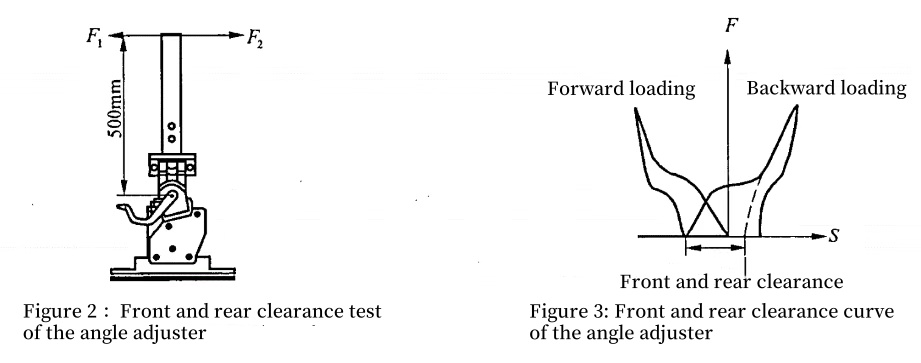
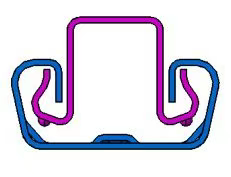
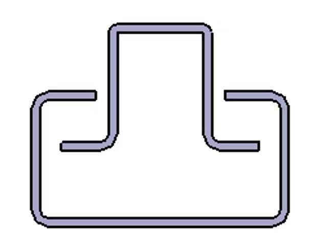
Fix the recliner assembly on the rigid fixture according to Figure 2, weld a rigid steel plate on the upper connecting plate, and evenly apply a forward force F1=200N perpendicular to the backrest at 500mm from the rotation center, and then release it evenly; then evenly apply a horizontal backward force F2=200N, and then release it evenly to obtain the F-S curve. According to Figure 3, draw a tangent along the upper part of the backward loading curve. The distance between the intersection with the S axis and the starting point of the backward loading is the front and rear clearance of the recliner. The front and rear clearance of the recliner should not be greater than 3.5mm.


2) Lateral clearance of the recliner

 Lateral clearance of the recliner


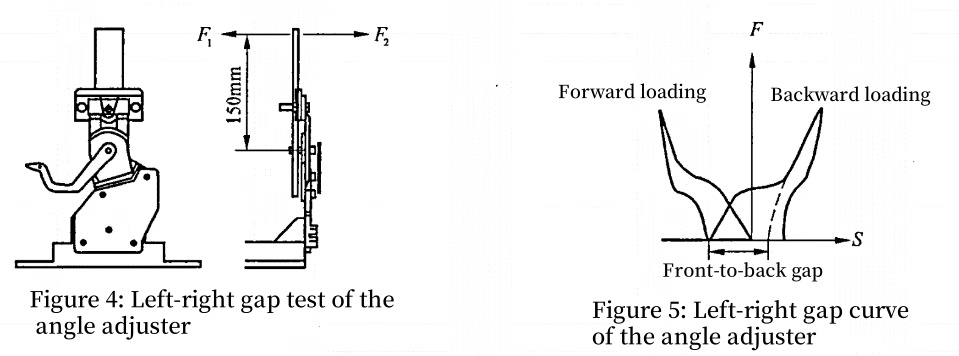
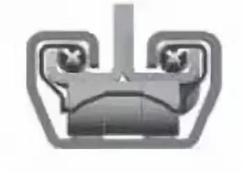
Fix the recliner assembly on a rigid fixture according to Figure 4, weld a rigid steel plate on the upper connecting plate, apply a force F1=100N perpendicular to the backrest to the left at a distance of 150mm from the rotation center, and then release it evenly; then apply a horizontal force F2=100N to the right evenly, and then release it evenly to obtain the F-S curve. Draw a tangent along the upper part of the right-hand loading curve according to Figure 5. The distance between the intersection with the S axis and the starting point of the right-hand loading is the lateral clearance of the recliner. The lateral clearance of the recliner should not be greater than 1.5mm.


3) Manual recliner sliding gear speed

Fix a simulated backrest frame assembly with an idle stroke recliner on a rigid fixture, place the simulated backrest in the front position, and lift the simulated backrest upward to ensure that the angular velocity of the simulated backrest is 180°/s when it reaches the first meshing position. The test result should be able to lock at the first tooth position.


4) Manual recliner operating force


 Manual recliner operating force


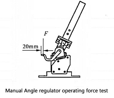
a. Discontinuous manual recliner

Fix a complete discontinuous manual recliner simulating the backrest assembly on a rigid fixture. According to Figure 6, at 20mm from the end of the handle, use a dynamometer to pull the handle in the unlocking direction vertically. The dynamometer reading when the backrest is just unlocked is the unlocking force, and the unlocking force range should meet 19.6N~80N.


b.Continuous manual recliner

Fix a complete continuous manual recliner simulating the backrest assembly on a rigid fixture. Use a torque wrench to drive the handwheel at a uniform speed. The reading of the torque wrench is the operating torque. The test results of the simulated backrest assembly in any position and under no-load conditions should meet 1 Nm~3Nm.


5) Manual recliner handle misoperation force


 Manual recliner handle misoperation force

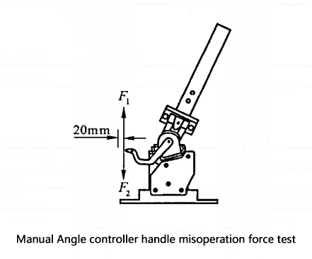
Fix a simulated backrest frame assembly on a rigid fixture according to Figure 7, lift the handle upward, add the lifting force to 200N and hold it for 5s. After releasing the force, the recliner is required to function normally. According to Figure 7, a simulated backrest frame assembly is fixed on a rigid fixture, and the handle is pressed down to increase the downward pressure to 300N and maintained for 5s. After releasing the force, the recliner is required to function normally.


6) Recliner forward and backward static load strength

a. Recliner forward static load strength

A recliner assembly is fixed on a rigid fixture, and a rigid steel plate not shorter than 300mm is welded on the upper connecting plate. A forward pulling force is applied to the upper end to ensure that the torque generated by the pulling force is 600N·m, and it is maintained for 5s without abnormal phenomena such as breakage and excessive deformation. (If the upper plate is twisted during loading, an auxiliary hinge can be added to improve the stability of the test)


b. Recliner backward static load strength

A recliner assembly is fixed on a rigid fixture, and a rigid steel plate not shorter than 300mm is welded on the upper connecting plate. A backward pulling force is applied to the upper end to ensure that the torque generated by the pulling force is 800N·m, and it is maintained for 5s without abnormal phenomena such as breakage and excessive deformation. (If the upper plate is twisted during loading, an auxiliary hinge can be added to improve the stability of the test)


7) Impact strength of the recliner


Impact strength of the recliner


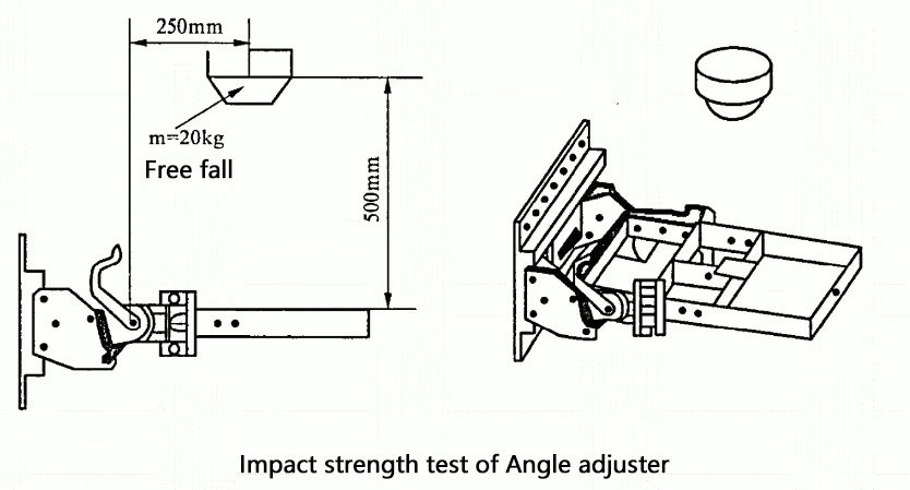
Fix a simulated backrest frame assembly on a rigid fixture according to Figure 8, and let a 20kg weight fall freely from a height of 500mm. The impact position is at the center of the backrest 250mm away from the rotation center. It is required that there is no abnormal phenomenon such as breakage or excessive deformation after the impact.


8) Front and rear limit strength of the recliner

Fix a simulated backrest frame assembly on a rigid fixture, adjust the simulated backrest to the front or rear position and keep the recliner unlocked, apply a torque of 245N·m forward and backward respectively, and keep it for 5s without abnormal phenomena such as breakage or excessive deformation.


9) Durability of alternating load of recliner

A simulated backrest frame assembly is fixed on a rigid fixture, and the simulated backrest frame is adjusted to the designed position. Alternating loads of forward torque F1 = 147N·m and backward torque F2 = 294N·m are applied to the middle of the simulated backrest upper rod in sequence. Each time the forward and backward loading is completed is a cycle. After a total of 15,000 cycles, the angle change of the upper connecting plate should not exceed 1.5°, and the entire recliner assembly has no abnormal phenomena such as breakage, excessive deformation and functional failure.


10) Durability of manual recliner operation

 Durability of manual recliner operation


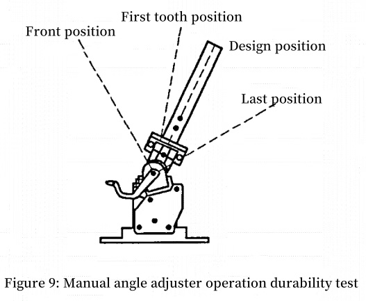
Fix a simulated backrest frame assembly on a rigid fixture according to Figure 9, adjust the simulated backrest frame to the first tooth position, and follow the first tooth position → last position → design position → front position → first tooth position as a cycle. Each position must have locking and unlocking steps. After completing 8,000 cycles, the recliner assembly should function normally without obvious deformation and mechanical damage. The flat scroll spring return torque attenuation rate should not exceed 15%, the recliner operating force change should be within 15%, the front and rear clearance of the recliner should be less than 3.85mm, and the lateral clearance should be less than 1.65mm.


For the simulated backrest frame assembly of the recliner without idle travel, there is no first tooth position. Follow the design position → last position → front position → design position as a cycle, and the rest of the process is the same.


11) High and low temperature performance of the recliner

a. Place the recliner assembly in an environmental test chamber, adjust the ambient temperature in the chamber to -40℃ and +80℃ respectively, keep the temperature for 4 hours, and then place the recliner assembly to room temperature. The recliner assembly should have no abnormal phenomenon.


b. Place the recliner assembly in an environmental test chamber, adjust the ambient temperature in the chamber to -29℃ and +70℃ respectively, keep the temperature for 4 hours respectively, and operate the recliner in the corresponding environment. The recliner assembly can complete at least one working cycle without grease dripping.


c. Place the recliner assembly in an environmental test chamber, adjust the ambient temperature in the chamber to -29℃ and +70℃ respectively, keep the temperature for 4 hours respectively, and then adjust the chamber temperature to room temperature. Operate the recliner. The running speed change of the recliner assembly should be less than 25%, and the running noise increment should be less than 3dB(A).


12) Lateral stiffness and clearance of the unlocking handle of the manual recliner

 Lateral stiffness and clearance of the unlocking handle of the manual recliner


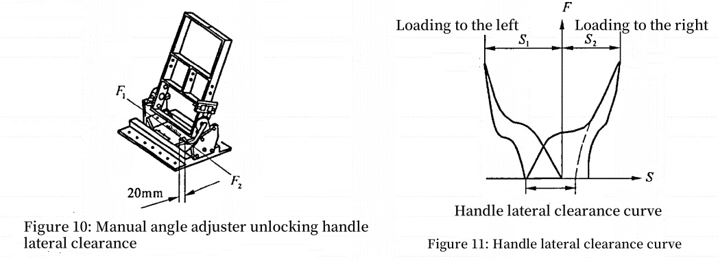
Fix a simulated backrest assembly on a rigid fixture according to Figure 10, and apply a horizontal force F1=49N to the left at 20mm from the end of the handle, and then release it evenly; then apply a horizontal force F2=49N to the right, and then release it evenly to obtain the F-S curve. The maximum deformations are S1 and S2 respectively. Draw a tangent along the upper part of the rightward loading curve according to Figure 11. The distance between the intersection with the S axis and the starting point of the rightward loading is the lateral clearance of the handle. The total deformation S=S1+S2 should not be greater than 15mm. If only one side is forced, the deformation S1 or S2 should not be greater than 10mm, and the lateral clearance of the handle should not be greater than 2mm.


13) Maximum angular displacement of the unlocking handle of the manual recliner

Fix the recliner assembly with a handle on a rigid fixture, and use an inclinometer to measure the angular displacement of the handle from the initial position to the maximum unlocking position. The maximum angular displacement should not exceed 40°.


14) Running speed of the electric recliner

Fix the simulated backrest assembly with the electric recliner on a rigid fixture, add a 45kg weight at a distance of 245mm from the rotation center, test the voltage to 12.6V (coil resistance is not greater than 0.2Ω), use a stopwatch to measure the time t1 taken by the backrest to move from the last position to the front position, and then measure the time t2 taken by the front position to move to the last position. The recliner stroke divided by the obtained time t1 and t2 is the running speed ω1 and ω2 of the electric recliner. Within the entire adjustment stroke, the running speeds ω1 and ω2 of the electric recliner should meet 2°/s ~ 6°/s.


15) Electric recliner vibration


 Electric recliner vibration


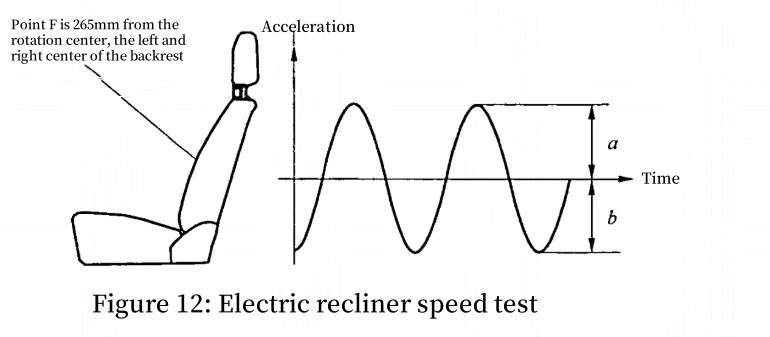
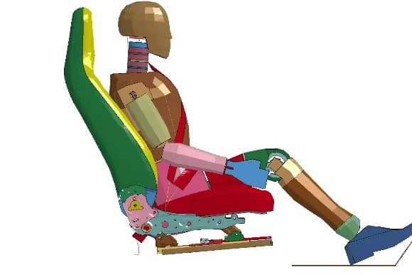
Fix a complete seat on a rigid fixture according to Figure 12, fix a 30×30×1mm small steel plate at point F, fix an acceleration sensor on the small steel plate (range: 0~500Hz), voltage 12.6V (coil resistance not more than 0.2Ω), adjust the recliner, within the adjustment range, the vibration acceleration ((a+b)/s ) should not be greater than 5.88m/s^2.


16) Electric recliner noise

Fix a complete seat on a rigid fixture, add a 45kg weight at 245mm from the rotation center, test voltage 12.6V, place a decibel meter on the center plane of the seat 635mm above point H and 100mm behind the seat, adjust the seat when the ambient noise is below 35dB(A), and the noise should not be greater than 53dB(A) during the entire movement range.


17) Operational durability of electric recliner

 Operational durability of electric recliner


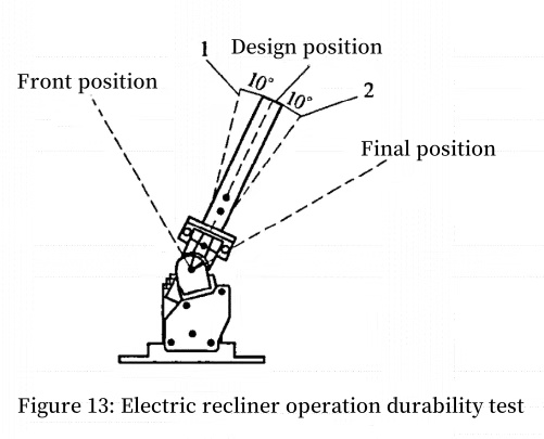
Fix an electric recliner simulation frame assembly on a rigid fixture according to Figure 13, add a 45kg weight at a distance of 245mm from the rotation center, adjust the simulated backrest frame to the designed position, test voltage 12.6±0.5V, repeat the test with one full stroke and three partial strokes as one cycle, and complete a total of 2,000 cycles (full stroke is: designed position → last position → front position → designed position; partial stroke is: designed position → 2 → 1 → designed position, and the electrical appliance is allowed to be sufficiently cooled during the test), there should be no obvious deformation and mechanical damage, the front and rear clearance of the recliner should be no more than 3.85mm, and the lateral clearance should be no more than 1.65mm.


18) Overload protection of electric recliner assembly


 Operational durability of electric recliner


As shown in Figure 13, fix an electric recliner simulation skeleton assembly on a rigid fixture, add a 45kg weight at a distance of 245mm from the rotation center, operate the recliner to the front and rear positions at a voltage of 14.5V, and no abnormality occurs in the recliner assembly.


Under a voltage of 12V, the recliner assembly should be able to start running from the front and rear limit positions. After adjusting the recliner to the front and rear limit positions respectively, continue to energize the recliner assembly to overload it, record the time from the start of overload to the occurrence of power-off protection, and the test results should meet the following requirements.


The electric recliner assembly runs to the limit position at a voltage of 14.5V, and no abnormality occurs in the recliner assembly. Under a voltage of 12V, the recliner assembly should be able to start running from the limit position. When the recliner assembly is overloaded, there should be overload protection, and the time from overload to power-off protection should not exceed 20s.

Looking for the Best EV Charging Solution?

As the popularity of electric vehicles (EVs) continues to grow, so does the demand for efficient, reliable, and adaptable charging solutions. Whether you’re a private EV owner, fleet manager, or business looking to invest in charging infrastructure, selecting the right charger is critical for ensuring the longevity and performance of your EV.


EV Charger with Adjustable Current: Flexibility for Every Vehicle

Our EV Charger with Adjustable Current offers a key advantage: flexibility. Unlike traditional chargers that come with a fixed current, this charger allows users to adjust the power output to suit their specific needs. Whether you are charging a high-capacity EV that requires fast charging or a smaller battery that needs a slower, energy-efficient charge, this charger can be adjusted to meet those requirements.


This feature is essential for households or businesses with different EV models. It helps ensure that every vehicle is charged optimally, avoiding damage to the battery from overcharging or inefficient charging practices. With the adjustable current feature, your charging process becomes both faster and safer, prolonging the life of both the EV battery and the charger.


Three-Phase Electric Vehicle Charging: Efficiency and Speed

For those requiring faster charging, Three-Phase Electric Vehicle Charging is the ideal solution. Unlike single-phase chargers, which are commonly found in residential settings, three-phase chargers provide a higher and more stable power output. This results in faster charging times, especially in commercial or fleet settings where multiple EVs need to be charged simultaneously.


The three-phase system distributes power evenly across three phases, making it significantly more efficient and faster than traditional single-phase systems. Whether for business or residential use, the three-phase system ensures that your EV is charged quickly and reliably, improving the overall efficiency of your charging infrastructure.


Adjustable EV Charging Cable: Durability and Versatility

The Adjustable EV Charging Cable is another key component of our EV charging solutions. Designed for durability and ease of use, this cable allows you to easily switch between single-phase and three-phase charging systems. It is perfect for both home charging setups and public charging stations.


Our cables are built to withstand harsh weather and physical wear, making them ideal for long-term use in various environments. The flexibility of the adjustable cable ensures a reliable connection every time, and it allows users to adapt to different charging needs effortlessly.

  • Adjustable EV charging cable
  • Three-phase electric vehicle charging
  • EV Charger with Adjustable Current


B58 Gen2 EVO CNC Billet Intake Manifold A Game-Changer for BMW B58TU (48V) Engines

Hello, car enthusiasts! Today, we're diving deep into the world of high-performance engine components with a focus on the B58 Gen2 EVO CNC billet intake manifold. This piece of engineering marvel is designed specifically for BMW's B58TU engines, particularly those equipped with the 48V mild-hybrid system. Let's explore what makes this intake manifold a must-have upgrade for BMW owners.

 B58 Gen2 EVO 48V intake manifold


Understanding the B58TU Engine

Before we delve into the specifics of the B58 Gen2 EVO intake manifold, let's quickly recap the B58TU engine. This updated version of BMW's iconic B58 engine incorporates several enhancements, including compatibility with 48V mild-hybrid systems, improved thermal management, and refined turbocharger technology. These upgrades make the B58TU not only more powerful but also more efficient and environmentally friendly.


Introducing the B58 Gen2 EVO CNC Billet Intake Manifold

The B58 Gen2 EVO intake manifold is a premium aftermarket solution designed to take your B58TU engine to the next level. Here are the key features that set it apart:

 B58 Gen2 EVO 48V intake manifold


Increased Heat Exchanger Capacity

One of the standout features of the B58 Gen2 EVO manifold is its enlarged heat exchanger core. Compared to the stock B58TU (48V) intake manifold, the EVO version boasts a 20% larger heat exchanger. This enhancement significantly improves the cooling efficiency, ensuring that the intake air remains at an optimal temperature. Cooler intake air means better combustion efficiency, which translates to more power and improved fuel economy.


Precision CNC Machining

The intake manifold is crafted from high-quality billet aluminum using state-of-the-art CNC machining techniques. This ensures unparalleled precision and durability. The smooth, polished surfaces and optimized internal passages reduce turbulence, allowing for more efficient airflow into the engine. This not only boosts performance but also enhances the overall reliability of the component.

 B58 Gen2 EVO 48V intake manifold


Compatibility with BMW's 48V System

The B58 Gen2 EVO intake manifold is specifically designed to work seamlessly with BMW's 48V mild-hybrid system. This means you can enjoy the benefits of the upgraded intake without worrying about compatibility issues. The manifold is engineered to integrate perfectly with the vehicle's existing electrical architecture, ensuring a hassle-free installation.


Included Gasket Set

To ensure a perfect seal and prevent any air leaks, the B58 Gen2 EVO intake manifold comes with a comprehensive gasket set. These high-quality gaskets are designed to withstand the rigors of high-performance driving, providing a reliable seal that keeps your engine running smoothly.


B58 Gen2 EVO 48V intake manifold


Performance Benefits

Upgrading to the B58 Gen2 EVO intake manifold offers several tangible benefits for your BMW:

  • Increased Power Output: The larger heat exchanger and optimized airflow passages result in a noticeable increase in horsepower and torque across the entire RPM range.
  • Improved Fuel Efficiency: By maintaining cooler intake air temperatures, the engine operates more efficiently, leading to better fuel economy.
  • Enhanced Throttle Response: The improved airflow and reduced turbo lag make for a more responsive driving experience. You'll feel the difference the moment you press the accelerator.
  • Longevity: High-quality materials and precision manufacturing ensure that the intake manifold will stand the test of time, providing consistent performance for years to come.


If you're looking to unlock the full potential of your BMW B58TU engine, the B58 Gen2 EVO CNC billet intake manifold is a fantastic investment. With its enlarged heat exchanger, precision machining, and seamless compatibility with BMW's 48V system, this intake manifold is designed to deliver both performance and reliability. Whether you're a track enthusiast or simply want to enhance your daily driving experience, the B58 Gen2 EVO is a must-have upgrade.


Are you ready to take your BMW to the next level? Check out the B58 Gen2 EVO CNC billet intake manifold today and experience the difference for yourself!

Celebrating Chinese New Year

Celebrating Chinese New Year: A Festive Journey into Spring


With its vibrant festivities and deep cultural significance, the Chinese New Year, also known as the Spring Festival, is a much-anticipated celebration in China and among Chinese communities worldwide. Steeped in traditions that span centuries, this holiday marks the beginning of the lunar calendar and is a time for family gatherings, delicious feasts, and vivid displays of color and light. In this blog post, we'll delve into the essence of the Chinese New Year, exploring its customs, legends, and the joyous atmosphere that envelops communities during this auspicious time of renewal and hope.

Origins and Legends:
The Chinese New Year has a rich history dating back thousands of years. Legend has it that the holiday originated from the ancient fight against the mythical beast Nian, who would terrorize villages. Over time, various customs and rituals have been incorporated into the celebration, all with the intention of warding off evil spirits and bringing good fortune. As the customs evolved, the Chinese New Year became a joyful expression of hope, unity, and the promise of a fresh start.

Preparations:
Preparations for the Chinese New Year begin well in advance, as families clean their homes to sweep away bad luck from the previous year. This cleaning ritual symbolizes the welcoming of good fortune and prosperity. Another essential tradition involves decorating homes with red lanterns, couplets, and intricate paper-cuttings, all of which symbolize happiness, good luck, and warding off evil spirits.

Reunion and Family Traditions:
The spirit of togetherness is the core essence of the Chinese New Year celebrations. Family members gather from near and far to honor their ancestors, make offerings, and pay respects at family altars. The reunion dinner, also known as "nianyefan," is a highlight of the festivities. This lavish meal features a wide variety of dishes, each with symbolic meaning, such as fish for abundance and dumplings for wealth.

Red Envelopes, Fireworks, and Dragon Dances:                                                                                          One beloved tradition during the Chinese New Year is the distribution of red envelopes, or "hongbao." Typically filled with money, these envelopes are given to children and unmarried individuals as a symbol of good luck and blessings for the coming year. Fireworks also play a significant role, with their explosive displays believed to drive away evil spirits. Dragon and lion dances captivate spectators as performers weave their way through the streets, accompanied by the rhythmic beats of drums and cymbals.

Lantern Festival:
The festivities of Chinese New Year conclude with the Lantern Festival, held on the fifteenth day of the lunar calendar. Parks and streets are adorned with beautiful lanterns of various shapes and sizes. Traditional performances, riddle games, and lantern displays create a magical atmosphere, marking the end of the Spring Festival celebrations.


The Chinese New Year is much more than a holiday; it represents a cultural tapestry woven with deep-rooted traditions and a boundless sense of hope and renewal. The joyous atmosphere, colorful decorations, and delectable feasts make this celebration a truly unforgettable experience. Whether you participate in the vibrant parades, share in the joy of family reunion, or immerse yourself in the captivating legends, the Chinese New Year invites people from all walks of life to embrace its warmth and be enthralled by the spirit of togetherness that transcends time and borders.


How Many Seats Are on a Bus

When it comes to buses, the first question people ask is “How many seats are there on a bus?” The number of seats on a bus can vary greatly depending on the type of bus and its intended use. In this article, Xiamen Van Seat will explore different types of buses and their seating capacity, and how we are changing the bus seating industry through our innovative design and commitment to comfort to enhance the travel experience of users.

 bus seat


Factors that affect seating capacity

Bus design: The layout and design choices of different manufacturers affect the seating arrangement.

Amenities: Some equipment features in the vehicle can reduce the total number of seats, such as onboard toilets, wider seats, and extra legroom.

Safety regulations: There are restrictions on the maximum number of passengers in different places, which are usually limited to around 56 seats in the United States.


The seat capacity varies for different buses

Standard buses

Standard buses are usually used to carry a large number of passengers for long-distance travel or intercity transportation, so its typical number of seats is about 50, but the actual number of seats may be 36 to 60. And the seating arrangement of buses of different widths is usually in rows, with two or three seats in each row.


School Bus

The seats in school buses are mainly for students in the school, so the seats are designed with high backrests and small spacing to minimize movement during transportation. Therefore, the capacity of school buses is about 48 to 72 seats.


Shuttle Bus

Shuttle buses are designed for short-distance travel, generally used for airport transfers or local transportation within the city. Shuttle buses usually have 12 to 30 seats and are equipped with additional facilities such as air conditioning and Wi-Fi.


Tour Bus

Tour buses have large windows, comfortable seats, and even restroom facilities. They are used for sightseeing and long-distance travel and usually have about 40 to 60 seats.


Proper planning based on seating capacity can help prevent overcrowding and contribute to a more pleasant travel experience. Whether you need seats for a standard bus, school bus, shuttle bus or tour bus, Xiamen Van Seat has a solution for you.Visit our website www.luxuryvanseat.com to explore our range of bus seats and other vehicle seating solutions.

Is a rotating car seat worth it

As families look to the safety and convenience of their vehicles, they are asking themselves, “Are swivel car seats worth it?” Swivel car seats are a great innovation in the car seat industry, offering comfort, convenience, and accessibility. Let’s take a look at the benefits of swivel car seats to help you make an informed decision.

 Rotating car seat


What is a swivel car seat?

A swivel car seat is a swivel design on the seat base that allows it to swivel toward the door. It is ideal for people with physical limitations or those managing naughty toddlers who don’t want to sit in a car seat, without bending or twisting to buckle them.


Key Benefits of a Swivel Car Seat

• Ease of Use

The swivel mechanism allows the seat to swivel toward the door, making it easier for users to place their child in or out of the seat, reducing the amount of effort required and simplifying the buckling process.


• Enhanced Accessibility

For families with children or caregivers with disabilities, the swivel feature of a swivel car seat makes entry and maneuvering easier, reduces awkward movements when children are getting in and out of the car, and provides better accessibility for people with physical disabilities.


• Convenience

Swivel car seats save time and effort, making the process of getting your child in and out of the car seat quicker and easier.


Potential Disadvantages of Swivel Car Seats

• Higher Price

Swivel car seats are usually more expensive than traditional car seats. This is because of the additional features and mechanisms that provide the swivel function.


Swivel car seats are a worthwhile investment, and while the seat costs more, they provide long-term benefits and great convenience, safety, and accessibility. Xiamen Van Seat has a range of high-quality swivel car seats, if interested in purchasing, please visit www.luxuryvanseat.com.